Mechanical members stay distinct so the assembly can be reviewed without a body shell obscuring the working geometry.

Move from adesign question to adefensible answer.Move from adesign question to adefensible answer.
One offline Windows workspace for rapid component sizing, connected system studies, engineering assurance and traceable preliminary design.
63solver workbenches
289modes across all solvers
8engineering disciplines
100%local project control
Connected vehicle development
See the assembly.
Understand the response.
Vehicle Dynamics brings suspension geometry, steering, articulation controls, calculated graphs, and synchronized 2D/3D engineering views into one focused assembly.
 Vehicle Dynamics Assembly
IncludesSuspension CAD·Motion playback·Calculated graphs
SCREENING / REVIEW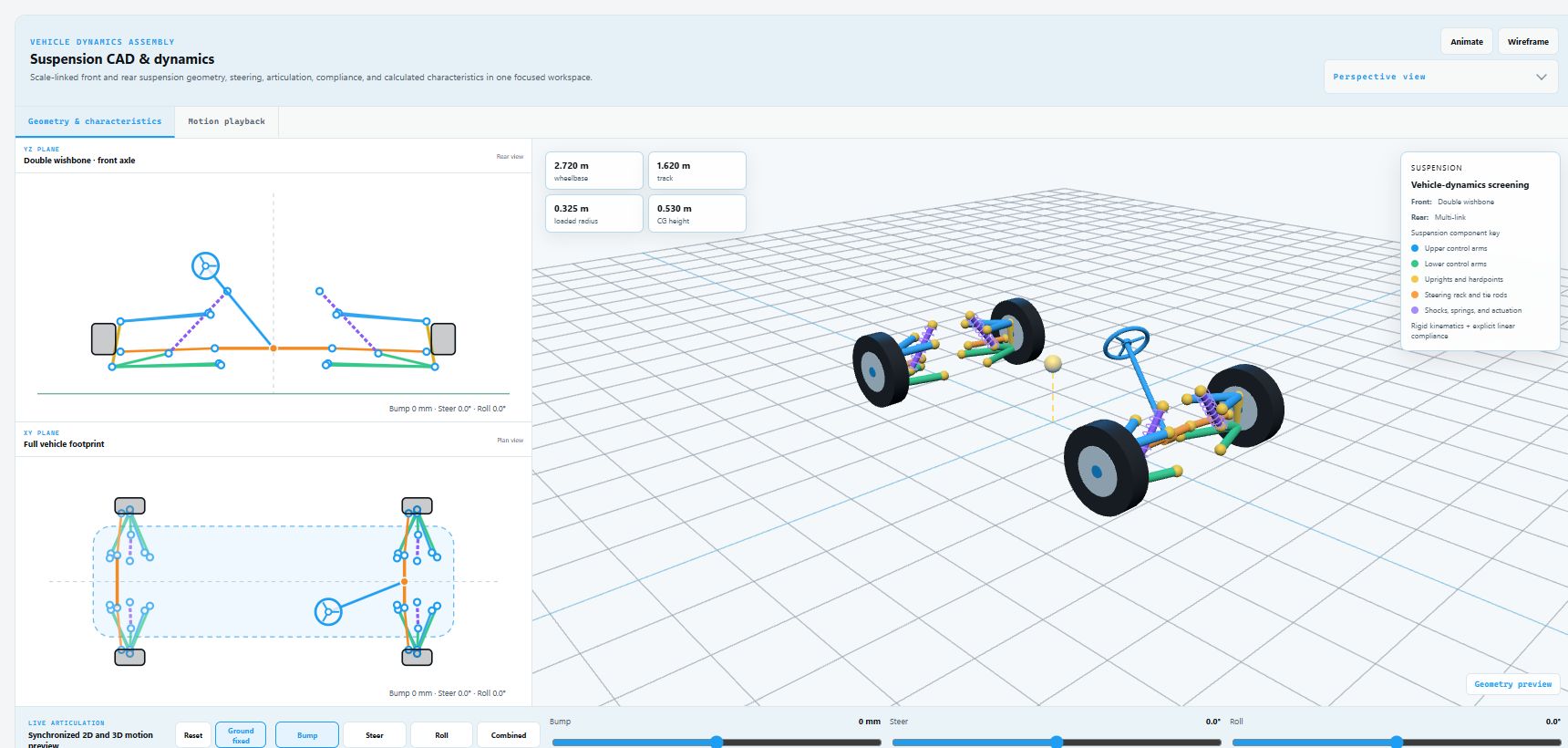
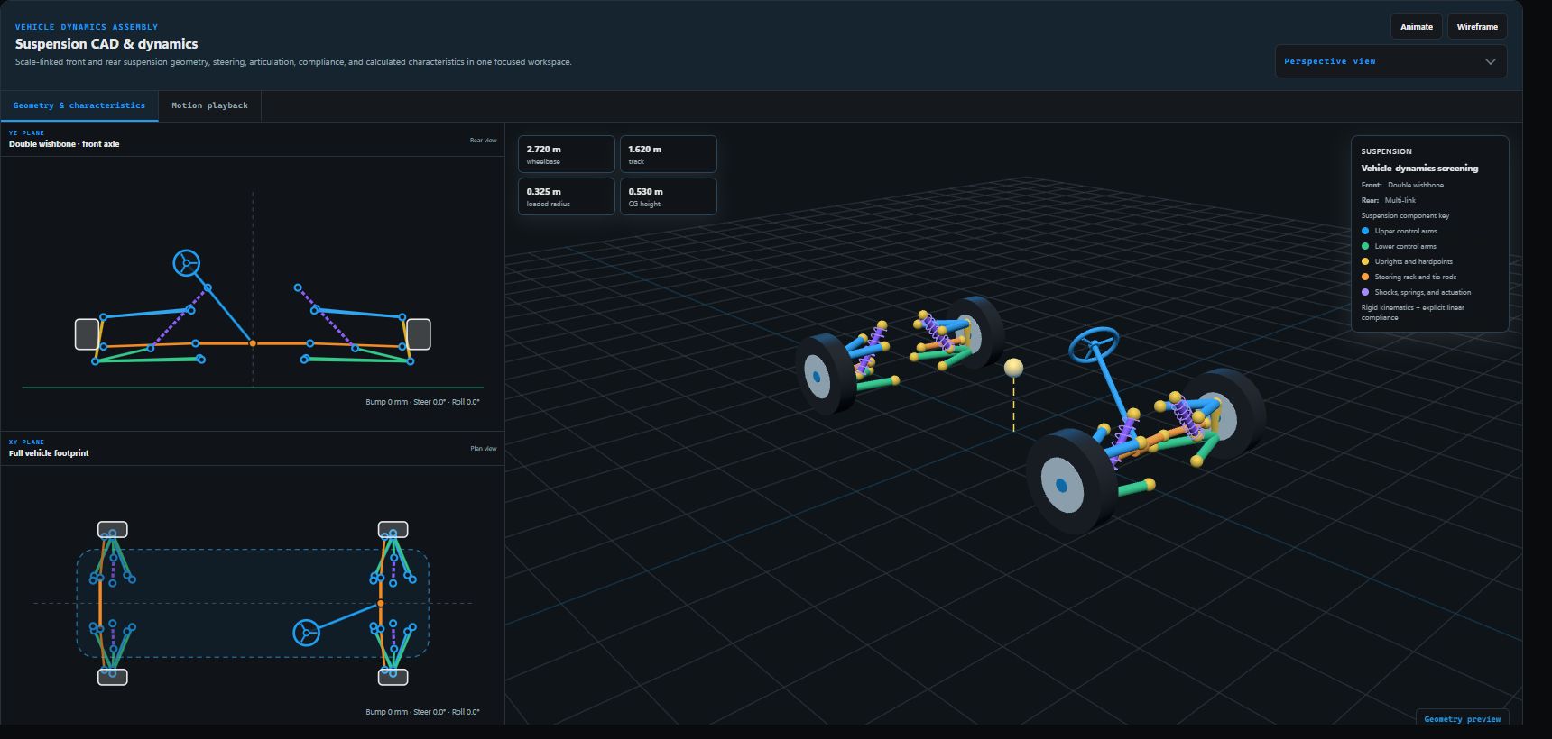
Bump, roll, steer, and combined articulation use one synchronized review workflow across the available views.
Calculated characteristics and response graphs remain tied to the active assembly inputs and review state.
02Open one subsystem.
From assembly to evidence
Open one subsystem.
See what the geometry changed.
The assembly is not a disconnected visual. MetraBench carries its suspension definition into the component calculation, then returns the trends, margins, and review state to the same vehicle record.
Calculated suspension component
Read the response.
Keep it tied to the assembly.
These coordinated curves use the released Vehicle Dynamics baseline: double-wishbone front, multi-link rear, and a ±75 mm rigid-link jounce sweep. Every axis, series, unit, and review boundary remains visible.
FRONTDouble wishboneREARMulti-linkSWEEP−75 to +75 mmFIDELITYScreening / Review
From question to record
A workflow built for
engineering judgment.
MetraBench keeps the calculation, its context and its evidence together—from the first estimate through design review.
Define
Set project units, standards, safety factors, materials and shared load cases.
Calculate
Choose from guided solver modes with engineering-aware input checks.
Review
See governing margins, assumptions, warnings, equations and evidence status.
Document
Save revisions and export a traceable calculation package for review.
Spur Gear SolverCalculated graphs · Production defaultsReal solver evidence
See how geometry changes load, stress, margin, and speed.
This is the current Spur Gear Solver graph workspace rendered directly in the browser. Follow the blue default marker across the four views: a 20-tooth pinion drives a 60-tooth gear under 120 N·m input torque.
RATIO3.000 : 1PITCH DIAMETERS60 / 180 mmMESH FORCE4.00 kNBENDING REVIEW0.82 SF · Below target
Broad by design
One workbench.
Eight disciplines.
Replace scattered spreadsheets, bookmarks and single-purpose calculators with a consistent, project-aware engineering environment.
General
Unit conversion, uncertainty, sensitivity, comparison and reusable engineering foundations
Mechanical
Machine elements, drivetrains, fasteners, shafts, bearings and motion
Structures
Beams, columns, sections, joints, pressure vessels and fatigue
Fluids + thermal
Piping, pumps, hydraulics, heat transfer and thermal systems
Automotive
Suspension, tires, braking, aerodynamics, ride and transient handling
Manufacturing
Machining, welding, quality, sheet metal and tolerance analysis
Electrical
Circuits, motors, batteries, controls, sensors and power
Operations + quality
Production flow, process capability, reliability and quality engineering
Calculation reports
The result.
The reasoning.
The record.
Keep the problem definition, calculated results and selected graphs together in one readable report.
- Start with the inputs.Loads, operating conditions, units and targets stay with the calculation.
- Show what governs.Failed checks remain visible alongside the results and engineering context.
- Carry the evidence.Selected graphs, assumptions and the equation source complete the record.
Testing-version layout · Real default calculation
Sample only; not a customer project.
MECHANICAL ENGINEERING / SAMPLE REPORT
Bearing operating-life report
Deep-groove ball bearing · Individual operating conditionFAILAdjusted rating life is below the 20,000 h target.
| Result | Value |
|---|---|
| Bearing familySelected rolling-element arrangement | Deep-groove ball |
| Adjusted rating lifeReliability and manual operating-condition modifier applied | 9,259.3 h |
| Equivalent dynamic load PEquivalent load for the individual operating condition | 5.000 kN |
| Equivalent static load P0Static load for the individual operating condition | 5.000 kN |
| Required dynamic rating CFor the selected target life | 64.633 kN |
| Static safety C0/P0Screening ratio; required value is application-specific | 8.000 |
Showing 6 of 21 results. The complete sample includes the full calculation context.
Current workbench catalog
Explore the engineering
workbenches.
63solver workbenches
289modes across all solvers
Start with a curated selection from the current desktop registry. Expand the complete catalog when you need to search all 63 workbenches and 289 selectable calculation modes.
Spur, helical, bevel, worm, rack, internal, herringbone, and planetary geometry, force, strength, and ratio screening.
Acceleration, grade, range, drag, cooling, steady-state handling, load transfer, transient yaw, sideslip, and stability.
Rolling-bearing rating life, load factors, lubrication, and static safety plus separate hydrodynamic plain-journal pressure, PV, film, clearance, and heat screening.
Beam reactions, shear, moment, stress, slope, deflection, vibration, and Euler buckling.
Multilayer conduction, convection and radiation boundaries, heat duty, interface temperatures, U-value, and transient thermal response.
AC/DC power, voltage drop, motor acceleration, battery runtime, and transformer fault current.
Two-plane reactions, combined stress and fatigue, required diameter, deflection, twist, buckling, and critical speed.
Rack-and-pinion travel, steering ratio, Ackermann wheel angles, turning circle, tie-rod geometry, and driver-effort screening.
Dimension-checked mechanical, thermal, fluid, electrical, and time unit conversion.
Monte Carlo tolerance propagation, confidence intervals, and sensitivity ranking.
Questions
Know where
MetraBench fits.
Is MetraBench a replacement for FEA or CFD?+
No. MetraBench is designed for rapid sizing, screening, system studies and traceable preliminary calculations. High-fidelity simulation and physical testing remain essential where the design risk requires them.
Does it require an internet connection?+
Core calculations and local project work are designed to run offline. This helps teams retain control of sensitive project information.
Can calculations be reviewed later?+
Yes. Projects preserve calculation context, revisions, assurance information and report-ready engineering records.
Which platform will be supported first?+
The initial release is designed for 64-bit Windows as a signed desktop application and installer.
MetraBench for Windows · Coming soon
Build faster.
Review with confidence.
MetraBench is being prepared for its first public Windows release. Early-access participants will receive product updates, release timing, and instructions when preview availability opens.
Windows desktopInitial platformLocal-firstProjects remain on your systemScreening / ReviewHonest engineering fidelity